 |
Projects
|
Projects Welcome To KenSeibert.Com Audio
Once you have the board in hand, the next task is finding all the necessary parts. Below is a parts list for the HV Power Supply part numbers and approximate pricing. Feel free to use your favorite parts... this list is just a suggestion and is meant to aid the person in collecting the parts.
ESL HV Power Supply Bill of Materials
| Ref Des | Part No | Description | Source | Qty Req | $ Each |
| C1-C10 | 594-S203M75Z5UN63J0R | Ceramic Cap, 20nF, 1000V | Mouser | 10 | 0.25 |
| C11 | 72-VY2103M63Y5UG63V0 | 300V AC Snubber | Mouser | 1 | 0.24 |
| C12 | 140-REA102M1ABK1012P | 100uF Electrolytic | Mouser | 1 | 0.16 |
| C13 | 77-VJ1206V105MXATBC | 0.1u 50V 1206 SMD ceramic | Mouser | 20 | 0.06 |
| D1-D10 | 583-1N4007-B | General Purpose Rectifier, 1000V | Mouser | 10 | 0.03 |
| D11-D12 | 78-LL4148 | General Purpose Diode, SMD | Mouser | 2 | 0.10 |
| D15 | 625-RS1A-E3/5AT | General Purpose Diode, SMD | Mouser | 1 | 0.10 |
| IC1 | 727-CY8C24123A-24PXI | Cypress PSoC Microcontroller | Mouser | 1 | 2.40 |
| LED1 | 604-WP7113SRD/E | Red T1 LED | Mouser | 1 | .10 |
| J1-J4 | 571-282857-2 | Phoenix Terminal Blocks - 3 Pos, 5.08mm | Mouser | 4 | 0.95 |
| J5 | 571-1-2199298-2 | 8-pin DIP Socket | Mouser | 1 | 0.09 |
| R1 | 66-CMO1/23601JLFTR | 3.6K Ohm 1/4W | Mouser | 1 | 0.08 |
| R32-33 | PPCHHJ11MCT-ND | 11M Ohm, 3500V | Digikey | 2 | 0.45 |
| R4, R12 | 71-CRCW0805-100K-E3 | 100K Ohm 0805 SMD | Mouser | 2 | 0.08 |
| R5, R8, R14 | 71-CRCW0805-1.0K-E3 | 1K Ohm 0805 SMD | Mouser | 3 | 0.08 |
| RLY1 | 653-G5LA-1-E-CFDC5 | General Purpose Relay | Mouser | 1 | 1.39 |
| RLY2 | 849-CPC1017N | Claire Solid State Relay | Mouser | 1 | 0.85 |
| T1 | 553-FP230-25 | Triad Isolation transformer | Mouser | 1 | 11.61 |
| T1 | 553-FP230-25 | Triad Isolation transformer | Mouser | 1 | 11.61 |
| U1 | 919-RAC02-05SC | 5V Integrated Power Supply | Mouser | 1 | 12.78 |
| Printed Circuit Board | KenSeibert.Com | 1 | 14.00 |
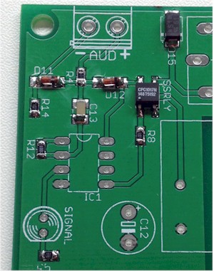
In general the strategy to board assembly is to solder on the smallest parts first. In this case, I like to start with the Surface Mount components. Please do not be afraid of working with these tiny parts. Once you get the hang of it, you will find them easy to use. I have a tutorial on working with these parts that you might find helpful. The photo below shows the board after the SMD parts have been installed.
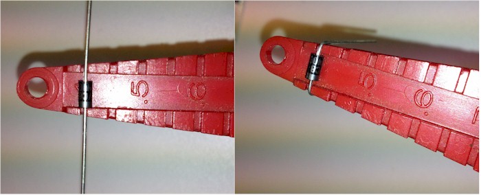
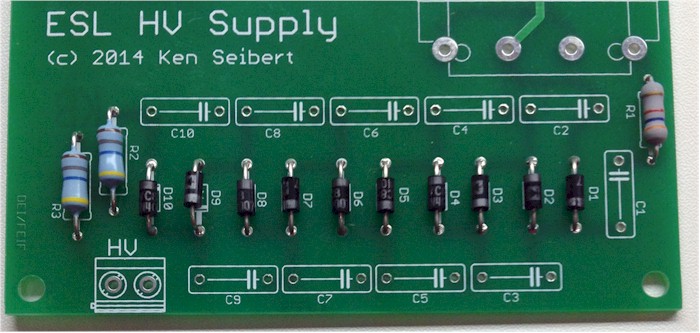
Next is to install the low profile, 2-leaded parts - resistors, diodes, etc. I find it helpful to use a lead-bending gauge to get consistent length bends. I think it makes for a better looking end product. One is certainly not required, but they are inexpensive enough, around $5 at most electronics stores. Techni-Tool, Jameco, and others make them. I have had mine for about 30 years and have no idea where I got it.
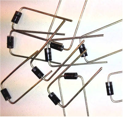
I usually bend all the leaded parts at once to go more quickly with the assembly
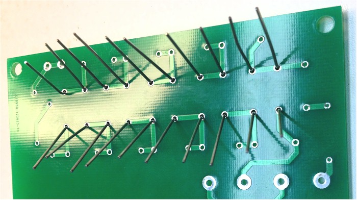
Insert a few of the parts into the approprite slots, then hold them as you tip the board over. The parts will tend to fall out of the holes on the board unless you bend the leads slightly outward. This keeps the parts snug to the board for soldering.
With the board lying face down, apply the soldering iron to the junction of the lead of the part and the solder pad on the board. Let it heat up for a second or two, then apply a small amount of solder. Keep the iron in place until the solder has flowed to cover the pad and whet to the lead. Remove the iron and let the solder cool without moving the lead or board.If the lead moves while the solder is cooling, you may get a weak joint that may fail in the future. If so, re-apply the iron until the joint is smooth and shines, then let it cool again. Adafruit has great illustrations of common soldering problems and how to repair them. The photo below comes from their site.

After the the parts have been soldered, trim the leads close to the board. This completes the small parts.
Repeat this process for progressively larger parts, like the small IC socket then connectors, relays, transformers amd finally the large caps.
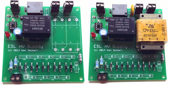
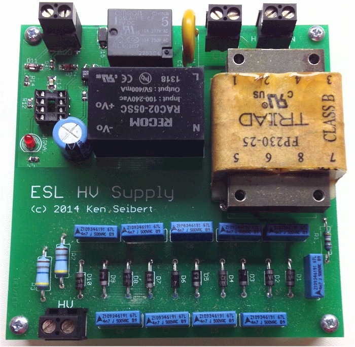
When all done, it should look like this:
Sometimes soldering leaves a residue of flux on the board. If you use a solder meant for electronics (non-acid, pure rosin flux) there is no need to clean the flux from the board. In faact it leaves a thin protective layer over the solder joints, but can be non-attractive visually. If you used a water-clean flux solder, then you must clean off the residue using water. The residue is hygroscopic and the scum-like layer can absorb moisture and conduct electricity. If you do use a flux cleaner, remember that they are not "spray-and-wipe", you need to use a brush (a tooth brush works well, just don't use it on your teeth afterwards).
If you would like to purchase a compete kit of parts, or a fully assembled and tested board, please visit the Store.