Welcome To KenSeibert.Com Audio
Testing the board can be tricky using the equipment most electronics hobyists have on-hand. The main problem is that most hand held voltmeters have a limit of 1000V DC, and we need to measure a few times that amount. The solution is to build a high voltage probe.
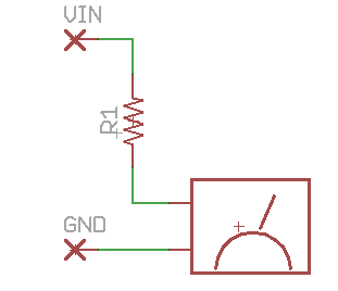
If you check the specifications on your voltmeter, you will probably discover that the input impedance of the meter is 10MOhms, or another similar figure. We will create a voltage divider with the meter as the resistor in the divider such that we will have approximately a divide by 10.

If the meter has a 10MOhm input impedance and R1 is 90MOhms, then we have a divide by 10. As a part of this project, you will have purchased some 11MOhm resistors. You can put 8 of them in series to make about 90MOhms. I have on hand some 18MOhm resistors, 5 of which will make 90MOhms.
Now we need to calibrate the probe. Measure a point in your circuit that is within the voltage limits of your meter (without using your HV probe). For instance the junction of C2 and D2. You should measure about 640V depending on the voltage of your AC line (which can vary from 110 to 120V). Now measure the same point with your HV probe. You should measure about 64V. Depending on how accurate your meter's input impedance as compared to the spec, you may get a slightly different voltage. Use the measured voltage against the expected voltage to create a scaling factor.
For instance if you expected 64V and you measured 58V, then you know your HV probe is off by 58/64, so you need to multiply your HV probe reading by 64/58 (about 1.1) to get the calibrated result.
When you measure the HV output, remember that there are already two 11MOhm resistors in series with the output, so you will have to measure at a point before the resistors, or they will become part of your divider network!
 |
Projects